Genja is a software as a service (SaaS) platform, aimed at automating the configuration stage of Juniper LAN network devices. This is where it starts, as we have been heavily involved in large scale projects deploying 10-100’s of switches for our customers.
Latest Entries »
CDP
Vlan’s for Cisco VoIP handsets are automatically detected using CDP. So when you assign the voice VLAN to a switch it will only use the voice VLAN if the CDP is enabled on the switch or for that particular port.
If you have another brand of handset that does not support CDP then you may have to assign the VLAN on the handset.
QOS
Auto qos is a simple way to enable qos on a port with one command. This command is effectively a macro and can you see the all of the actual lines of commands by running the debug auto qos before running the auto qos command on the desired interface.
When running a trace route I came across a weird result, usually the first hop is that of the default gateway but this was not the case. The first hop a appeared to be an internal 10.*.*.* address which is not even in my IP range. I took to google and found that other users had experienced the same results but they all appeared to be cable internet users.
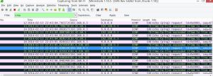
I then proceeded to carry out a wireshark trace to see if it would pick up any more information on the results. Then I learned that the tracer route appears to set the TTL field to one on the very first hop and after 3 pings (echos) increases the TTL=2 and so on… until the destination is reached.
So in the wireshark capture you will see destination response time to live exceeded.
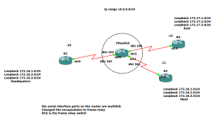
The image above is for a frame relay network with a hub and spoke topology.
I have made this the base config for the CBT route lab for EIGRP.
Looking at the image you can see I have made an ordinary router into a frame relay switch. The switch is the DCE end of the serial connection and is running in layer to as frame relay does not use IP addresses on the switch.
To turn on frame relay switching enter global config and enter: FRswitch(config)#frame-relay switching
This is just a quick over view as how the setup works on the frame relay switch (output from show frame relay route)
Input Intf Input Dlci Output Intf Output Dlci Status
Serial0/0 102 Serial0/2 201 active
Serial0/0 103 Serial0/1 301 active
Serial0/1 301 Serial0/0 103 active
Serial0/2 201 Serial0/0 102 active
As you can see the routes are mapped from the interface to a dlci which is local and mapped to the out going dlci.
On the frame switch in order to map the route you have to be in interface config mode in this example serial 0/0 then enter
FRswitch(config-if)#frame-relay route 102 int ser 0/2 201
Now I will move onto the other routers I will use the HQ router.
First we have to enable frame relay on the interface: HQ(config-if)#encapsulation frame-relay
Now we decide on the type of interface we would to configure a physical interface or a sub interface
Physical= split horizon is disabled by default
Sub interface= split horizon enabled by default
** Split horizon means that is a route is learned on ta particular interface it will not resend the routing information back out of the port. In this case as interface serial 0/0.1 is a multicast and would need to send the data back out when EIGRP is enabled.
Multicast = allows for the interface to have multiple connections with in the same subnet preserving IP addresses.
Point-to-point= uses one subnet per connection.
e.g HQ(config)#int ser 0/0.1 multipoint
Then configure the interface with an IP address and map the local dlci 103 in this case to the end destination ip address west router
e.g HQ(config-subif)#frame-relay map ip 10.0.0.11 103 broadcast
**Broadcast= psuedo broadcast
The broadcast command allows the router to form neighbours when running EIGRP as frame relay is non broadcast NBMA.
link to a better explanation
Sometime ago I came across a vlan mismatch and being the engineer that I am, I tried to fix it! The funny thing is there were no reported faults and everything was working, I just wanted to work my magic.
As I was studying for the CCNP I thought it would be a great opportunity to implement some of my studies being, PPDIOO ( prepare plan design implement operate optimize). I tried to cover all the steps starting from finding out what was causing the fault making notes as I went along right down to the verification commands I was feeling confident.
So I started putting in the commands and everything appeared to be working the native vlan mismatch had gone away and now I could relax. Just as I decided to log off the router I forgot one vital step, verification! I tried to ping the switch from the router, and I got nothing. I just thought ICMP had a delay and tried again but nothing. This was not good as this network was for a VOIP network and any drop in the network will be seen straight away compared to data. I couldn’t think what I had done wrong and the quickest fix was to reboot the router and hope the connection was restored, and it was. I had failed!
But in writing this blog it has helped me as I have gone away and logged on to the router and switch,everything appears to be working but there is an identical setup on a another router and switch setup which has one command that is different. No CDP run on the switch that isn’t displaying any faults and the other has cdp running now from what I can see at the moment but not confirmed yet is the other switch is masking the message.
The native Vlans are all the same but the switchport access vlan appear to be different as the switch is solely used for voip.
To test my theory I will disable cdp on the the switch that is throwing out the faults and vice versa. My impression now is that the message being put out is not a native vlan mismatch but a access vlan issue. Therefore the error message is incorrect and confusing but as I have continued studying for the CCNP it shows it takes a bit of time and experience.
%CDP-4-NATIVE_VLAN_MISMATCH: Native VLAN mismatch discovered on FastEthernet0 (1), with Switch_1 GigabitEthernet0/1 (20).
I have verified my theory and when I enabled CDP on the other router it started displaying native vlan mismatch. So even though the native vlans were both 1, CDP still flagged up an error because of dissimilar access vlans numbers
Subnet mask /32 255.255.255.255
Now the other day while I was completing some tasks at work I was asked for the subnet mask for an ADSL connection. My first instinct was that it was your normal ADSL connection and the IP address, subnet mask and all other relevant details are all assigned dynamically by the provider. But I decided to investigate and find what the subnet mask was, so I logged into the system to check and I saw a mask of 255.255.255.255. Thinking this couldn’t be right I picked up the phone and made a call to the provider, they said it was 255.255.255.255 also they asked how many I address I had and I replied 1. I asked are you sure because it looks as if you are looking at the same information that I’m looking at and to my knowledge a subnet /32 is not valid as there wouldn’t be any IP addresses available. The person replied that the information is correct, previous to this when I first had doubts on the subnet mask they had gone away to clarify the subnet was correct and we continued the conversation.
So trying not to be rude as they were the supplier of the ADSL connection I ended the call thinking this can’t be correct and thought I should take to Google and do some research.
What did I find! Subnet /32 255.255.255.255 is common on ADSL connection as it preserves the IP address and as the client is technically not in a network with anyone other than the ISP/ADSL provider there is only one way for the WAN traffic to go, to the provider.
- Subnet mask 255.255.255.254 /31
When I first saw this subnet mask I wanted to say what you cant you that because there is no network address or broadcast to even be a valid subnet. Furthermore it stated in the CCNA that you can only go to /30 for a point to point connection. But I held myself back as it came from someone who has been doing this for much longer than myself, so I Googled it and to my surprise you could.
The way a /31 255.255.255.254 subnet work is they use half the public IP addresses compared to /30 255.255.255.252. In point-to-point deployments, there is no need for a broadcast and network addresses as there is only one possible route for the traffic.
There is more information int the RFC 3021
This feature was first introduced in the Cisco IOS 12.2.(2)T. When you assign a 255.255.255.254 subnet on a Cisco, it will give a warning saying as point-to-point IP subnet is being assigned to a port that may not be point to point.
For all the latest in formation about Cisco certification.


